Below, our main research topics are described briefly. More and more new accomplishments will follow, and we will update this page occasionally.
Currently, we are mainly conducting research on thermo-fluid dynamic issues related to propulsion. These engines are used for automotives, airplanes and rockets, where thrust is generated by converting thermal energy into kinetic energy. It is important to enhance the fuel efficiency and reduce harmful emissions.
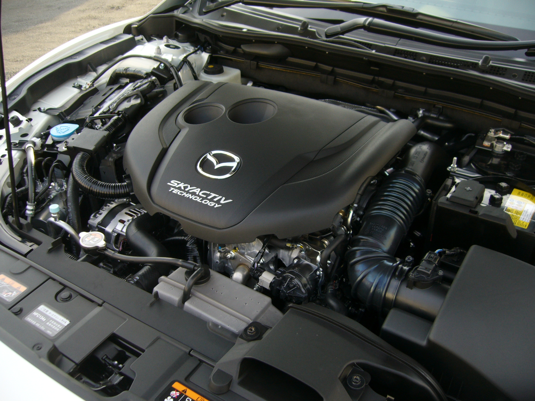
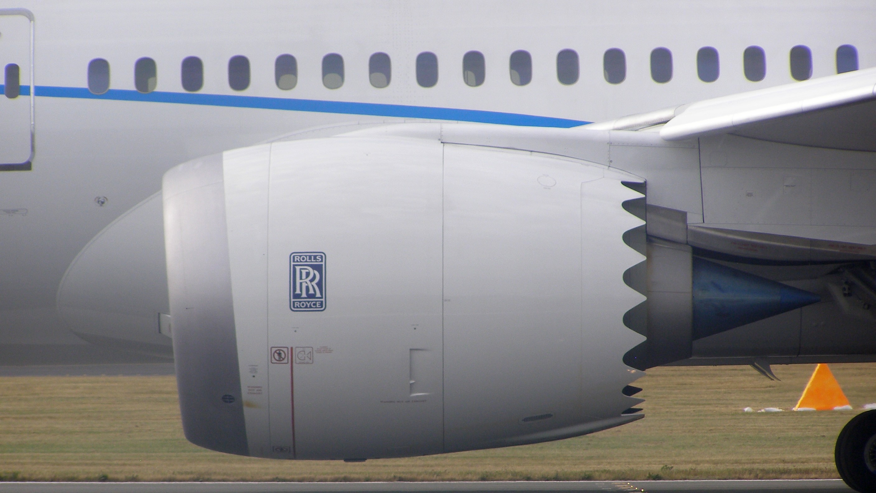
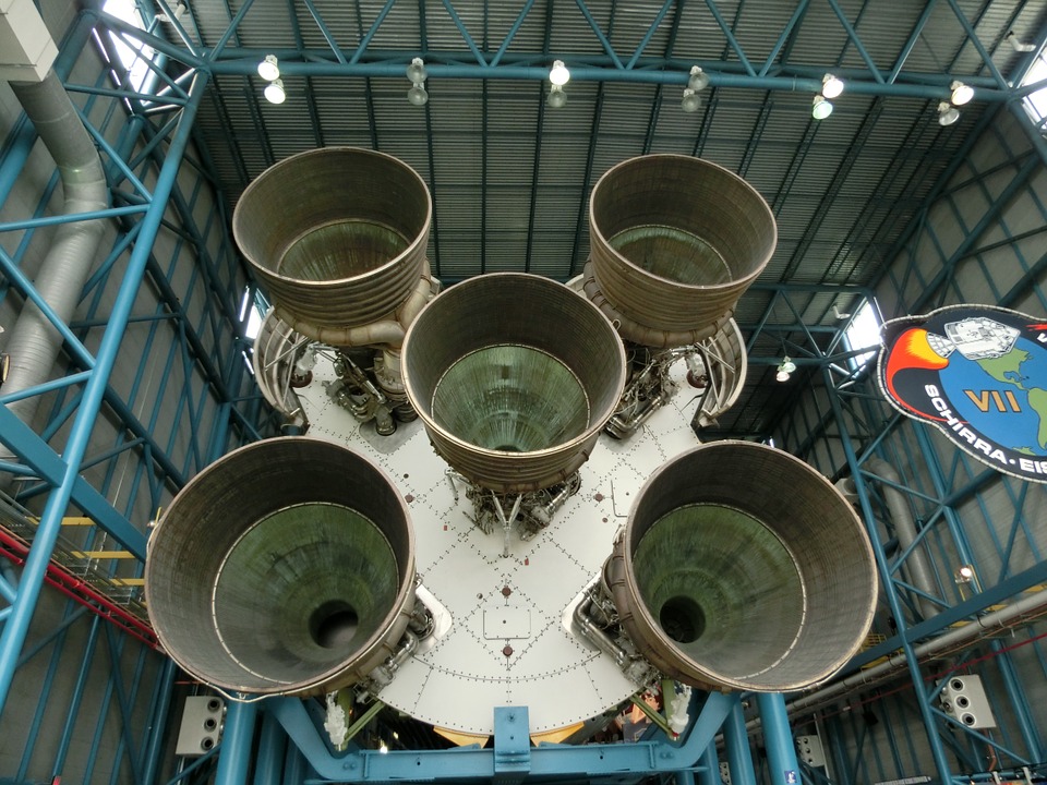
(From left; automotive engine (Mazda), aero-engine (Rolls Royce), rocket engine (Apollo mission))
Fluid Flow and Solidification Characteristics of Melted Metal
Liquid Fuel Spray Atomization
Biofuel Droplet Heating, Puffing and Combustion
Combustion Instability and Control
SUSANOO Model Jet Engine
Student Research Projects
Fluid Flow and Solidification Characteristics of Melted Metal
In the processing of various superalloys, melted metal behaves as a fluid. The behavior is similar to that of liquid fuels, but in addition, solidification and thermodynamic characteristics should be properly considered.
Here, an example of metal additive manufacturing (AM) is shown. AM is a manufacturing method in which laser is utilized to melt and solidify metal powders. Laser power, laser scanning speed, heat absorption and physical properties of target metals are important parameters. It is interesting to investigate topics such as formation/control of pores, vaporization characteristics and in-situ melt blending of several metals.
Figure 1 shows the melting and solidification process of Ni powders, simulated by using a laser ray-tracing method, which tracks the laser beam propagation, absorption and reflection. Due to the temperature rise, Ni powders melt and form a local melt pool. The liquid metal deforms due to the local pressure, surface tension and convective flow motion. During this process, vapor ejection also occurs. After the laser beam is scanned, the heated metal region gradually cools and solidify. This kind of detailed simulation is expected to identify appropriate parameter settings and to enable various manufacturing methods in industrial applications.
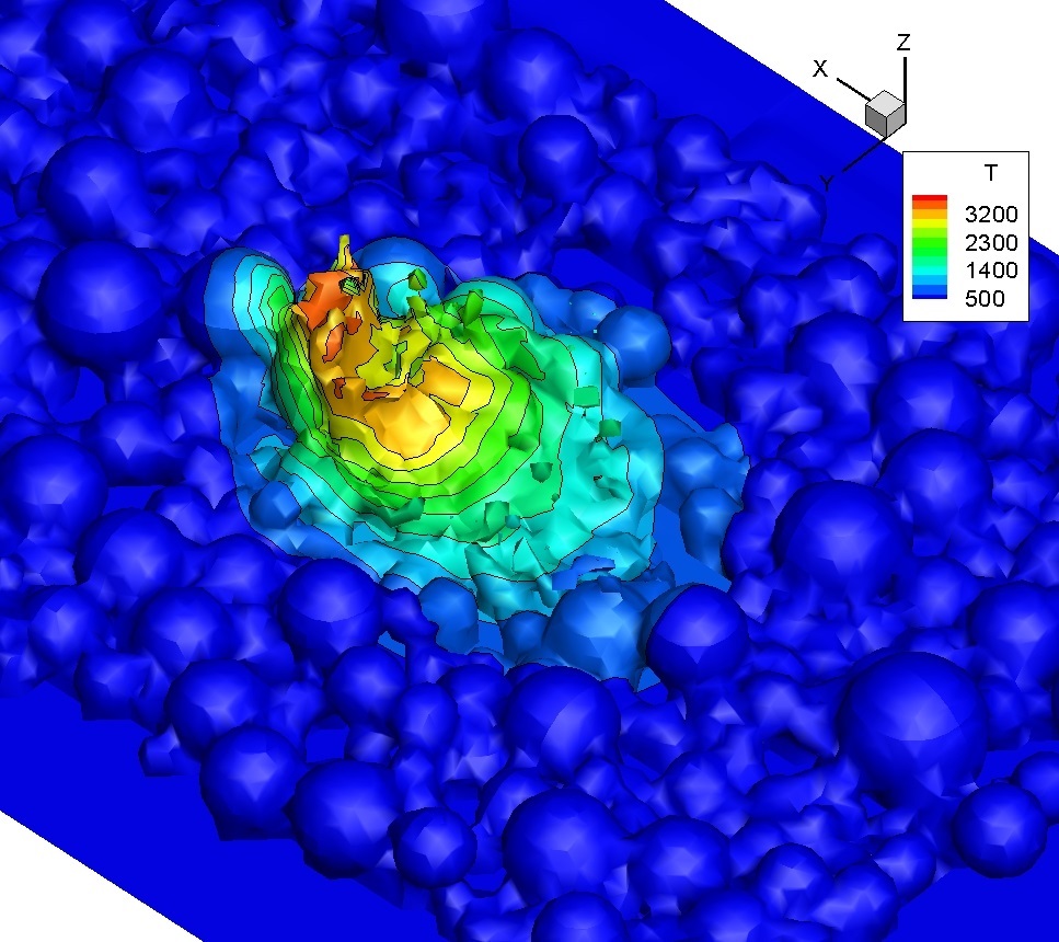
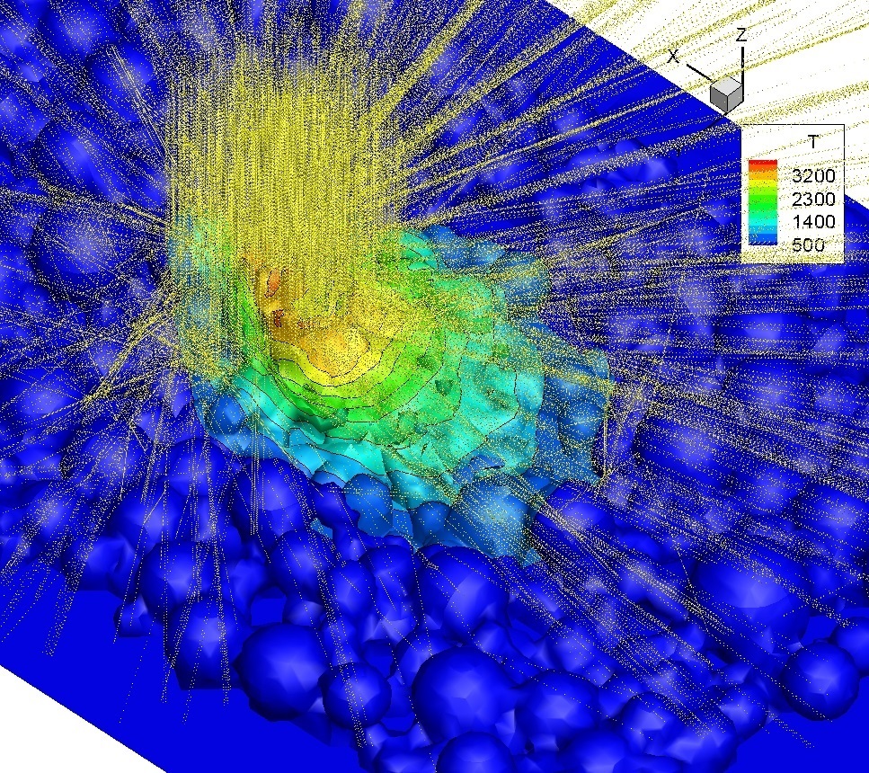
Fig. 1 Example of metal additive manufacturing (AM) or 3D printing. Here, Ni powders are melted. The surface color represents the temperature. Yellow loci indicate the laser rays tracked in the simulation. The laser beam is emitted in the –z direction, while being scanned in the +x direction.
- Relevant papers (See "Publications".)
Getley et al., Adv. Sci. 2026
Karan et al., Prog. Addit. Manuf. 2026
Zhang et al., Acta Mater. 2025
Dai et al., J. Mater. Process. Technol. 2025
Wu et al., Surf. Coat. Technol. 2025
Wannapraphai et al., J. Mater. Res. Technol. 2025
Aliyu et al., Eng. Fail. Anal. 2025
Mukherjee et al., npj Comput. Mater. 2024
Aliyu et al., J. Mater. Res. Technol. 2024
Zhang et al., Nat. Commun. 2024
Shinjo et al., Addit. Manuf. 2024
Dai et al., Int. J. Machine Tools Manuf. 2023
Aliyu et al., J. Mater. Res. Technol. 2023
Shinjo et al., Addit. Manuf. 2023
Aliyu et al., Int. J. Refract. Met. Hard Mater. 2023
Shinjo & Panwisawas, Addit. Manuf. 2022
Panwisawas et al., Addit. Manuf. 2021
Shinjo & Panwisawas, Acta Mater. 2021
Liquid Fuel Spray Atomization
Automotive or aircraft engines generally use liquid fuels because the energy density is sufficiently high and it is much easier to store and carry liquid fuels compared with gaseous or solid fuels. In the combustion chamber, the liquid fuel is injected at a very high speed to make a spray. This process is called atomization. By this, the total surface area can be increased significantly and subsequently, fuel vaporization and mixing can be enhanced. Liquid atomization has been used for a long time, but still, details of its physical processes have not been well revealed. Due to ever-increasing demands for greener combustion technologies, designing highly-efficient liquid-fuel systems is very important. Therefore, it is needed to understand the physical processes of liquid atomization in detail.
(1) Detailed mechanisms of liquid atomization (direct numerical simulation)
In this study, a Diesel fuel spray is investigated using DNS (Direct Numerical Simulation), in which the deformation and breakup of the liquid/gas interface is directly captured. The results have unveiled the jet head formation process due to liquid/gas impact, surface instability development leading to breakup (formation of ligaments), and droplet generation from the ligaments. Figures 2 and 3 show these processes.
Furthermore, in a subsequent study, evaporation has been incorporated to examine the process of fuel/air mixing, and to further correlate the turbulence/droplet interaction in a dense spray like this.
Currently, these valuable datasets are being used for modeling. We believe that the accuracy of spray combustion simulation could be much improved when our modeling is completed.
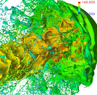
Fig. 2 Mushroom-like head formation due to liquid/air interaction. Ligament breakup is visible both from the head and from the liquid core surface.
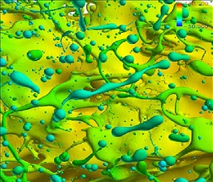
Fig. 3 Zoomed image of ligaments and droplets. Surface tension plays a critical role in the final droplet generation process from these ligaments.
- Relevant papers (See "Publications".)
Shinjo et al., Proc. Combust. Inst. 2015
Shinjo & Umemura, Proc. Combust. Inst. 2013
Shinjo & Umemura, Proc. Combust. Inst. 2011
Shinjo & Umemura, Int. J. Multiphase Flow 2011
Shinjo & Umemura, Int. J. Multiphase Flow 2010
(2) Detailed mechanisms of liquid atomization (experiment)
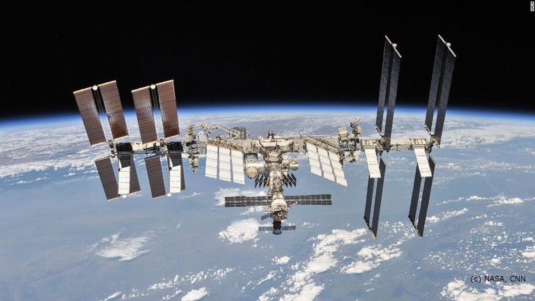
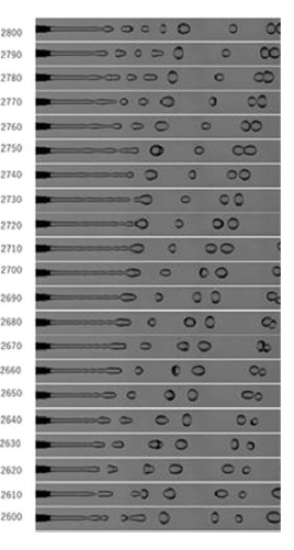
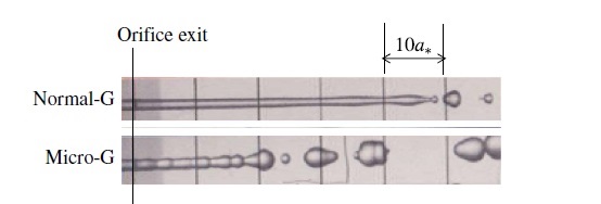
This is a joint study with Nagoya University and Japan Aerospace Exploration Agency (JAXA). We participate as a co-investigation institute in the space experiment "Detailed validation of the new atomization concept derived from drop tower experiments: Aimed at developing a turbulent atomization simulator" led by Prof. Umemura (Nagoya University). In this study, the mechanism of surface tension and capillary waves in atomization, especially in droplet pinch-off from a ligament, will be investigated under the micro-gravity conditions onboard the International Space Station (ISS). So far, such experiments have been conducted on the ground, forming a slow liquid jet vertically. Inevitably, the effect of gravitational acceleration is added in such a situation. The gravitational acceleration makes the liquid surface deformation unstable and this is superimposed on the intrinsic unstable mechanism due to surface tension. The conventional concept of surface destabilization has been misleading, and Prof. Umemura has proposed a new theory of self-destabilization due to capillary waves. This experiment is aimed to confirm the proposed mechanism, utilizing the micro-gravity environment on the ISS.
The experiment was conducted in 2018. Thanks to the microgravity environment, long observations were possible. In the photo, droplet generation is repeatedly observed due to the self-destabilization of capillary waves induced by the tip effect. The findings obtained in the present ISS experiment are utilized in atomization modeling.
 |  |
 |
- Relevant papers (See "Publications".)
Umemura et al., Microgravity Sci. Technol. 2020
Umemura, J. Fluid Mech. 2016
Umemura & Osaka, J. Fluid Mech. 2014
Umemura, Phys. Rev. E 2011
Umemura et al., Phys. Rev. E 2011
Shinjo & Umemura, Int. J. Multiphase Flow 2010
Umemura et al., J. Japan Soc. Aero. Space Sci. 2010
Umemura et al., J. Japan Soc. Aero. Space Sci. 2010
Shinjo et al., Atomization 2009
Shinjo et al., J. Japan Soc. Aero. Space Sci. 2007
(3) Spray modeling (spray simulation)
This is a joint study with Nagoya University, and also with Hokkaido University and Mazda. Simulations like the one in (1) (DNS) are accurate without models, but require a huge amount of computer resources, and the computational domain is inevitably limited. For spray simulations, DNS will not be a practical method. Modeled simulations, then, will be the best choice, but the modeling accuracy is a key issue. So far, the modeling accuracy of the primary atomization region (see (1)) has not been good, leading to a situation where parameter tuning is required using experimental reference data. In fact, this is a big problem that has hindered the full prediction capability of spray simulation.
In this study, we have incorporated a newly proposed turbulent atomization model, which has been proposed by Prof. Umemura (Umemura, Combust. Flame 2016)based on our past accumulation of physical knowledge on liquid atomization. Two atomization modes, turbulent resonant mode and Rayleigh-Taylor (RT) mode, are included. The spray code is a hybrid Euler-Euler and Euler-Lagrange large-eddy simulation (LES) code. Fortunately, the validity of the code has been demonstrated well.
The present method is novel in that
- the model does not contain any arbitrary model constants and no parameter tuning is needed, and
- it is physically consistent from the nozzle region to the downstream spray region.
Therefore, extension to further upstream, i.e. up to the inner-injector region, is possible.
Such a spray simulation code, with a fully closed atomization model, has not been possible so far. The present code leads to the drastically improved accuracy in predicting the spray and atomization characteristics, which is beneficial both for research and industrial purposes.
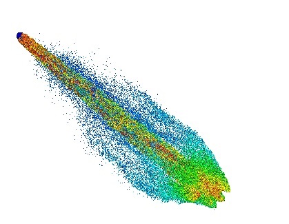

Fig. 5: Simulation of a Diesel jet (D=0.3mm, U=200m/s, cold flow) using the present method. The entire spray and the liquid core are shown respectively.
Making the ambient gas temperature higher, the evaporation and autoignition characteristics have been investigated. Due to turbulent atomization, a large number of droplets form a dense droplet layer surrounding the liquid core. This layer extends in the downstream region until the liquid core breaks up finally. Even when the ambient gas temperature is high, the heat cannot penetrate into the dense droplet layer, which leads to the sheath mode where the inner layer temperature is low and evaporation occurs only at the layer edge. The timing of autoignition is dependent on the ignition delay determined by the ambient gas temperature. When autoignition occurs in the vicinity of the spray, the gas flow is affected by the heat release and hence the spray development is also affected. Therefore, it is significantly important to predict spray development accurately, using a method like this, to improve the entire spray combustion characteristics.
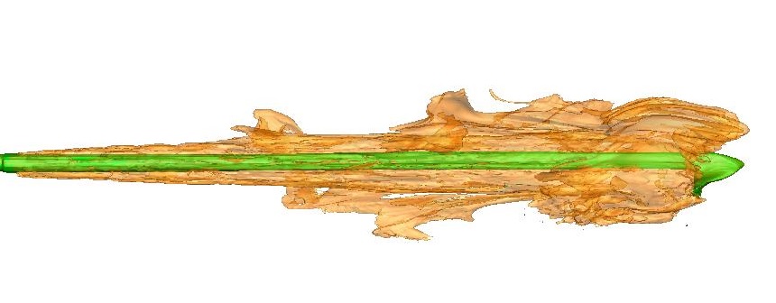

Fig. 6: Evaporation and autoignition of an early Diesel spray.
The left figure shows the temperature iso-surface of 600K with evaporation (without combustion) and the right figure shows the autoignited region by the red iso-surface of T=1500K.
- Relevant papers (See "Publications".)
Umemura & Shinjo, Proc. Combust. Inst. 2021
Shinjo & Umemura, Combust. Flame 2019
Umemura & Shinjo, Combust. Flame 2018
Umemura, Combust. Flame 2016
Biofuel Droplet Heating, Puffing and Combustion
In this study, we focus on biofuels, which are derived from vegetable oils, animal fats and other bio-origin substances. In total, it is believed that the emission of carbon dioxide (CO2) is offset. The physical properties of such biofuels are typically similar to those of fossil fuels. However, in detail, they are not the same. Currently, biofuels are used in a mixed form with fossil fuels. Therefore, it is needed to thoroughly understand the characteristics of biofuels for a better and efficient use.
In this study, droplets of combustor spray scale (~30 µm) are studied to mimic realistic flow conditions. A combination of (fossil) Diesel, bio-ethanol and bio-Diesel is used, resulting in a form of emulsion where ethanol is dispersed as tiny sub-droplets in the continuous (parent) phase of Diesel. Since the boiling temperature of ethanol is much lower than that of Diesel, when heated, ethanol may become superheated and, under some conditions, may boil explosively. This is called puffing or microexplosion, depending on the strength of the explosion. If puffing/microexplosion can be used positively, this can enhance secondary breakup and thus fuel vaporization and mixing. Again, DNS is used for investigating the detailed dynamics.
The results in Figs. 7 and 8 exemplify the effectiveness of this approach, yielding a lot of data on unsteady behavior of puffing, droplet breakup and vapor mixing. The case of a droplet group shown in Fig. 8 provides further new findings on droplet interaction under puffing conditions. Figure 9 shows the puffing-flame interaction. Currently, a subsequent modeling study is underway and is expected to improve the accuracy of spray simulation for biofuels in the near future.
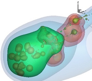
Fig. 7 Puffing and secondary breakup. Ejected vapor can be seen as red pockets.
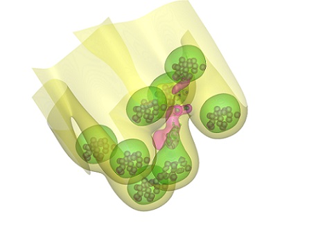
Fig. 8 Inter-droplet interaction in an emulsion droplet group. (Note that coloring is not the same as that in Fig. 7.)
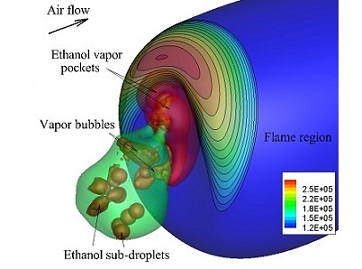
Fig. 9 Vapor/flame interaction. On the flame surface (shown as a blue iso-surface of T=1800K), the molar consumption rate of the ejected ethanol is superimposed.
- Relevant papers (See "Publications".)
Tanimoto & Shinjo, Fuel 2019
Shinjo & Xia, Proc. Combust. Inst. 2017
Shinjo et al., J. Fluid Mech. 2016
Shinjo et al., Atom. Sprays 2016
Shinjo et al., Phys. Fluids 2014
Combustion Instability and Control
To reduce NOx emissions from a gas turbine combustor, lean premixed combustion is one of the effective methods since the flame temperature can be lowered. (The generation of thermal NOx is due to the oxidation of N2 in the air, and the temperature is the primary parameter to determine its generation rate.) However, lean premixed combustion sometimes tends to be unstable, which, in an extreme case, leads to flame blowoff or causes mechanical damage to the combustor.
In this study, an active combustion control method is investigated. Experimentally, a model combustor has been setup and investigated using lean methane (CH4) as a primary fuel (Tachibana et al. Proc. Combust. Inst. 2007). A small amount of secondary fuel (pure CH4) is directly injected at the flame base to actively control the local heat release rate. A numerical study is also conducted by us to further understand the flame dynamics under control. The results reveal that the instability-sustaining loop among the pressure, velocity and heat release has been modulated by the control and thus oscillations are attenuated accordingly.
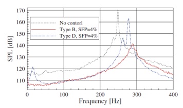
Fig. 10 Reduction of sound pressure level (SPL) by active control.(Tachibana et al. Proc. Combust. Inst. 2007)

Fig. 11 Flame dynamics with active control.
- Relevant paper (See "Publications".)
Shinjo et al., Combust. Flame 2007
SUSANOO Model Jet Engine
We are trying to develop a model jet engine in cooperation with a local company group SUSANOO. This is a small-scale engine with a centrifugal compressor, and we finally aim to "hot" run it. Students and young engineers will cooperate and share the fun of engineering such as designing and manufacturing.
SUSANOO companies are strong in machining alloys which are difficult to cut, and their expertise will be fully used in this project. Also, this project is conducted in cooperation with FOX Corporation. The figure below shows a CAD image of the engine.
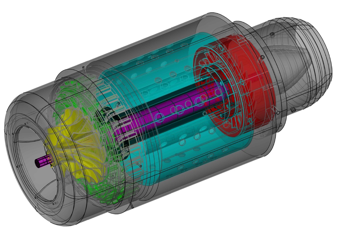
Fig. 12 CAD image of SUSANOO jet engine.
In some engine areas, the local gas temperature may become very high, especially from the combustor to the turbine. Here, we use Inconel 718, one of heat-resistant superalloys. For a region where the local stress will be high, Maraging steel is used. In contrast, Ti alloys and Al alloys are used to reduce weight for parts where heat or stress requirement is not strong. It is a good opportunity to learn metal selection, heat treatment and processing techniques.
The first firing test was conducted in April 2021. See the video below. This is a system test and the engine power is set very low. This time the maximum rotation speed is 13,000 rpm. At this power level, the flame is not fully contained in the combustor and can be seen in the video, but anyway the engine is well rotating. After this initial test, the engine is opened for detailed analysis. We have found several points for improvement.
The second firing test was conducted in October 2021. See the video below. This time, a self-sustaining test operation was achieved at 21,000 rpm. Therefore, the current engine design was basically demonstrated. We will continue design improvement for a better efficiency.
At the same time, we are conducting numerical simulation on compressor/turbine blade design. Findings from the simulation will be also utilized in the future design.
First firing test.
(Ignition is done from the exhaust exit. The fuel rate is gradually increased to reach 13,000 rpm and the engine operation is cut at 02:14.)
Second firing test.
(Ignition is done from the exhaust exit. From 01:22, self-sustaining operation is achieved at 21,000 rpm for about 20 seconds.)
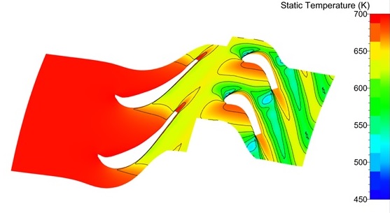
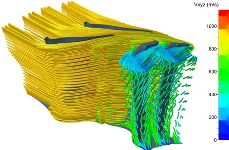
Fig. 13 Flow simulation around the turbine stator/rotor blades (temperature and streamlines).
Student Research Projects
<2024>
Master's thesis
・LES analysis of the effect of sub-saturation region distribution and bubble behavior on surface erosion in cavitation peening
Bachelor's thesis
・Numerical analysis of the effect of air cooling on human skin temperature
・Numerical simulation of vortex generators on a car body
・Simulation of wind damage on suger beet agriculture
・Evaluation of aerodynamic characteristics of a compact car body including underbody parts
<2023>
Master's thesis
・Visualization of tool wear progress with process state sphere in turning process
Bachelor's thesis
・Air drag reduction effect of rear spoilers on a hatchback automobile
・Effect of seams on aerodynamic characteristics of official balls used in American and Japanese professional baseball leagues
・Thermal evaluation of cooling methods on rocket nozzle wall surface temperature
・Effect of air bleeding on hypersonic air intake performance
・Change of flame and NOx generation characteristics due to combustion chamber pressure in a model hydrogen engine
<2022>
Bachelor's thesis
・Two dimensional simulation of the flow field around vertical axis wind turbine blades
・Numerical study of the effect of wing elevator on the flight performance of a paper airplane
・Flight stability control of an archery arrow by the gyro effect
<2021>
Bachelor's thesis
・Monitoring of cutting resistance in turning by using a piezobolt and semiconductor strain gauges
・Aerodynamic effect on bicycle riding by a passing automobile vehicle
・Turbine blade design for a small jet engine by computational fluid dynamics
<2020>
Master's thesis
・Fluid analysis around the centrifugal compressor/turbine blade of a small jet engine and guideline for improving the blade shape
Bachelor's thesis
・2D flow simulation of mixing in a compression ignition rotary engine
・Raindrop trajectory analysis for a motorcycle with variation in the head light shape
・On mixing enhancement of a high-speed jet and a low-speed flow due to a chevron
・Droplet distribution in a multi-layer mixing layer
<2019>
Bachelor's thesis
・Numerical simulation of high temperature jet from a non-round nozzle
・Aerodynamic simulation around front wings of a Formula-1 car following a preceding vehicle
・Behavior of volcanic ash particles inhaled into a jet engine combustor
<2018>
Master's thesis
・Interaction of droplets and turbulence in a shear flow by LES
・Numerical simulation of secondary atomization by explosive boiling of emulsion fuel for a free droplet and a sessile droplet on a wall
・Simulation of velocity fluctuation in liquid fuel due to cavitation and its influence on spray atomization
Bachelor's thesis
・Simulation of pollens removal by an air cleaner in a room
・Analysis of flight trajectory of a baseball by modeling aerodynamic characteristics of a rotating sphere with surface roughness
・Effect of amplitude and frequency modulation on mixing layer development
・Simplified simulation of knocking in a combustor
<2017>
Bachelor's thesis
・Numerical simulation of fundamental characteristics of laminar flames using CHEMKIN
・Aerodynamic drag characteristics and flow structures around large transportation vehicles in a tandem configuration
・Reduction of automobile aerodynamic drag by contracting the side body shape
・Numerical simulation of flows around turbine airfoils
<2016>
Bachelor's thesis
・Numerical simulation of air-blast atomization of liquid fuel
・Numerical simulation of an unsteady flow impinging on a solid body
・Numerical simulation of exhaust gas/air mixing in an incinerator
・Numerical simulation of a fast liquid flow in a pipe with a sudden contraction